Shell & tube heat exchangers offer large surface area in combination with efficient heat transfer and compactness. These are widely used in industries for various duties like cooling, heating, condensation, evaporation etc. GOEL are the pioneers in the field of glass shell and tube heat exchangers in India and their product has a wide market acceptability.
Salient Features of Shell and Tube Heat Exchanger :
1.Universal corrosion resistance an excellent alternative to expensive MOCs like graphite, hastelloy, copper titanium, tantalum and other exotic metals.
2. Excellent heat transfer as fouling does not occur on smooth glass surfaces.
3. Flexibility of installation vertical/horizontal.
4. Easy replacement of tubes for repair and cleaning.
5. Available in wide range of HTAs.
6. Ease of installation due to light weight.
7. Economical.
8. Suitable for applications where large HTAs are required in limited space.
Advantages of Shell and Tube Heat Exchanger Over Conventional Coil Type Heat Exchangers :
1. The overall heat transfer coefficient in shell and tube heat exchanger is about 3 times higher than in coil type heat exchanger.
2. The pressure drop in shell and tube heat exchanger is minimal compared to 2-3 kg/cm2 in coil side of coil type heat exchanger.
3. For requirement of higher heat transfer areas shell and tube heat exchanger is the only alternative.
Construction Features of Shell and Tube Heat Exchanger :
The glass tubes are sealed individually into PTFE tube sheet with special PTFE sockets and packing. This unique ferrule type sealing arrangement permits easy replacement and cleaning of tubes. Baffles on shell side ensure improved heat transfer by increased turbulance. Further details of construction can be seen in the diagram.
– Made from SCHOTT DURAN.
– Joint less tubes offer better pressure rating

TYPE:
Three basic versions * are available :
|
Material Of Construction of Shell & Tube Heat Exchanger |
||||
| Model | Shell | Tube | Header | Duty |
| RGG | Glass | Glass | Glass | For heat transfer between two aggressive media. |
| RGM | Glass | Glass | Steel/FRP | For heat transfer between aggressive media in shell & non-aggressive media in tubes. |
| RMG | Steel/FRP | Glass | Glass | For heat transfer between aggressive media in tubes & non-aggressive media in shell |
|
* GOEL provides assistance to clients for selecting the right model for specific duty. |
||||
* GOEL provides assistance to clients for selecting the right model for specific duty.
Dimensional Specifications of Shell and Tube Heat Exchanger :
|
Cat.Ref. |
6/3 |
6/4 |
6/5 |
6/6 |
9/6 |
9/8 |
9/10 |
9/12 |
12/12 |
12/16 |
12/21 |
12/25 |
|
Area (m2) |
3 |
4 |
5 |
6 |
6 |
8 |
10 |
12 |
12 |
16 |
21 |
25 |
| DN |
150 |
225 |
300 |
|||||||||
| DN1 |
80 |
100 |
150 |
|||||||||
| DN2 |
50 |
80 |
80 |
|||||||||
| DN3 |
25 |
40 |
40 |
|||||||||
| DN4 |
50 |
50 |
50 |
|||||||||
| H1 |
175 |
250 |
300 |
|||||||||
| H2 |
150 |
200 |
250 |
|||||||||
| L |
2500 |
3100 |
3700 |
4300 |
2620 |
3220 |
3820 |
4520 |
2550 |
3150 |
3950 |
4550 |
| L1 |
1900 |
2500 |
3100 |
3700 |
1900 |
2500 |
3100 |
3800 |
1800 |
2400 |
3200 |
3800 |
| L2 |
150 |
150 |
150 |
150 |
225 |
225 |
225 |
225 |
225 |
225 |
225 |
225 |
| L3 |
1600 |
2200 |
2800 |
3400 |
1450 |
2050 |
2650 |
3350 |
1350 |
1950 |
2750 |
3350 |
| L4 |
250 |
250 |
250 |
250 |
300 |
300 |
300 |
300 |
300 |
300 |
300 |
300 |
| L5 |
125 |
125 |
125 |
125 |
175 |
175 |
175 |
175 |
175 |
175 |
175 |
175 |
| L6 |
1980 |
2580 |
3180 |
3780 |
2000 |
2600 |
3200 |
3900 |
1930 |
2530 |
3330 |
3930 |
| T |
50 |
60 |
75 |
|||||||||
| No. of Tubes |
37 |
73 |
151 |
|||||||||
| No. of Baffles |
11 |
15 |
19 |
23 |
7 |
9 |
13 |
17 |
5 |
7 |
9 |
11 |

Range Of Applications :
Permissible temperature range for both shell & tube sides – 40째 C to 150째 C.
Maximum permissible temperature difference between shell & tube sides 120째 C.
All sizes & models are suitable for full vacuum on both side. Maximum limiting pressures are tabulated here below :
|
Maximum Permissible Pressure Range, Kg/cm2(g) |
||||
| Model |
Side |
150DN |
225DN |
300DN |
| RGG |
Shell |
2.0 |
1.0 |
1.0 |
| RGM |
Shell |
2.0 |
1.0 |
1.0 |
| RMG |
Shell |
3.5 |
3.5 |
3.5 |

The above ranges of applications are admissible limiting values. For each specific case GOEL recommends the admissible operating data based on the relations between pressure and temperature, size and model.
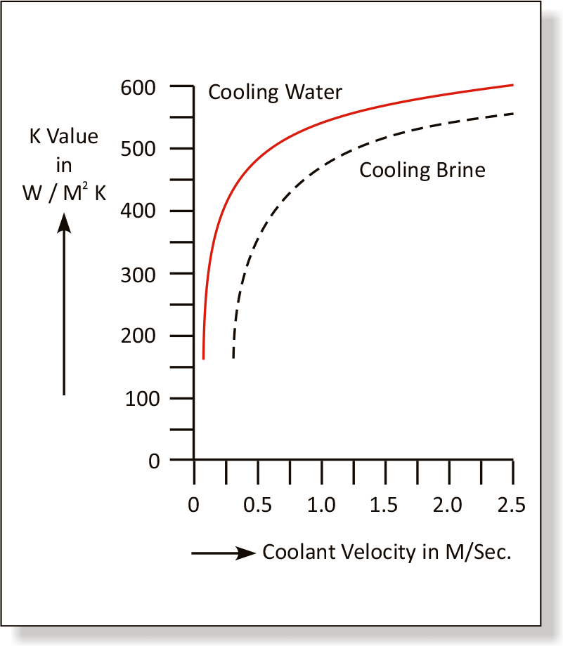
The particular advantage of shell & tube heat exchanger is high heat transfer performance. The relation between heat transfer and velocity of flow can be easily seen in the diagram. On receipt of the operating data from client the most favourable shell and tube heat exchanger is selected. This accurate design combined with most reliable quality assurance ensures economy and operational reliability for the user. For approximate sizing some typical heat transfer coefficients are given here below :
|
U-Values |
||||
| Media |
Use |
kcal/m2hrk |
W/m2k300 |
|
| DN | ||||
| Steam water |
condensation |
350-550 |
410-640 |
|
| Water – water |
cooling |
250-350 |
290-410 |
|
| Water – air |
cooling |
30-60 |
35-70 |
|